Lab 2: Multiplexed 7-Segment Display
Introduction
In this lab I created code, and testbenches to control two 7-segment display and used a multiplexer in order to display the two sides. A user can use the 2 DIP switches to control the two 7 segment display to show 0-F on the hexadecimal scale. As well as having the sum of the inputs together represented by 5 LEDs.
Technical Documentation
The source code for this project can be found in this github repository.
Block Diagram
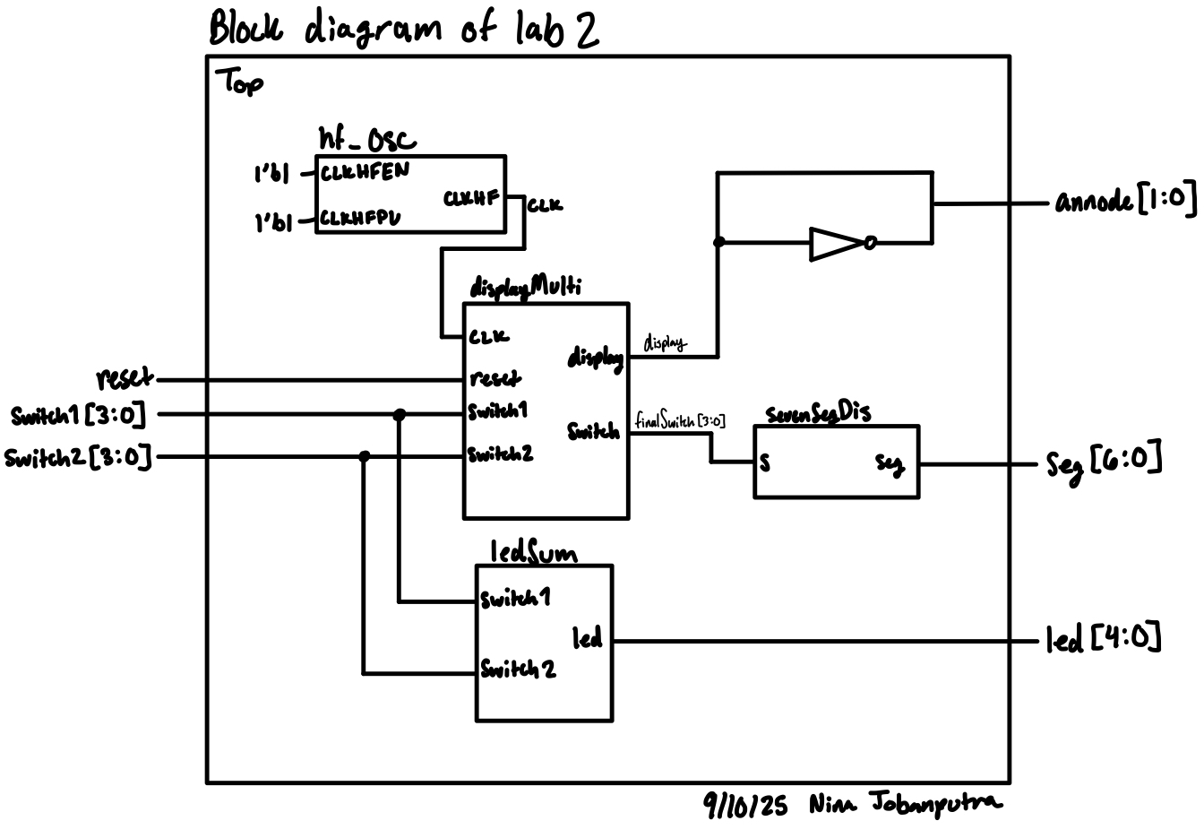
The block diagram in Figure 1 demonstrates the overall architecture of the design. The top-level module top includes 4 submodules.
Schematic
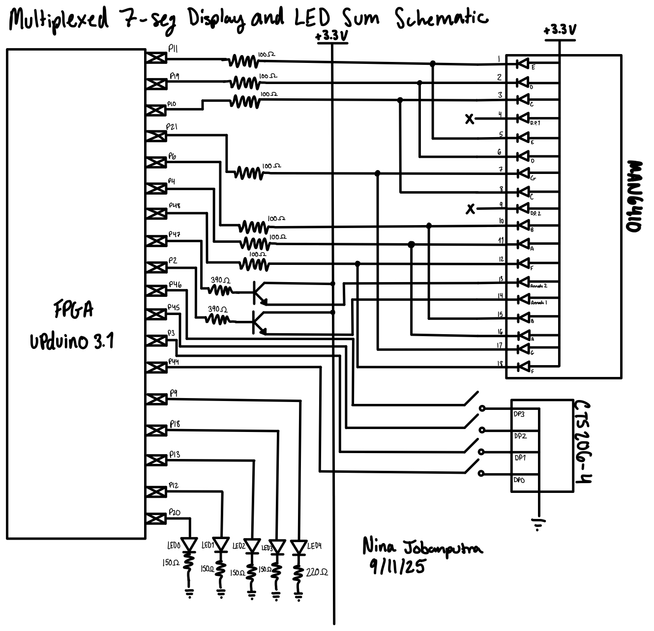
Figure 2 shows which pins were connected to the double 7 segment display and which parts and resistor values I used.
Finding Resistor Values
I had to use resistors for the transister. I used the datasheet provided in the lab and found that the V forward for the transistor was about 0.85V. I knew I was supplying 3.3V and current was 8 mA. Using Ohm’s law I got (3.3-0.85)/(8*10^-3) which gave me a resistor value of 306.25\(\Omega\). I then went to the stock room and found the only close resistor values we had were for 330\(\Omega\) and 390\(\Omega\). I would have gone with the 330\(\Omega\) but at the time there was only 1 resistor and I needed two. So I opted to go with the 390\(\Omega\) resistor. I redid my calculations to back track out current and found that the current was around 6.3mA which was an acceptable range for current.
I also had to use resistors for my LEDs and I used a similar calculation method and found that for the green LEDs I could use 150\(\Omega\) and the red LED I could use 220\(\Omega\).
Results and Discussion
I tested the circuit and I was able to get the simultaneous display. One hiccup I ran into was the pin out for the display module was a bit hard to read so I ended up accidentally rewiring one side of the display wrong. I believe in total I spent about 15 hours on this lab, which is a great improvement from last week.
Here are my outputs from my testbenches:
Seven Segment waves

DisplayMulti waves

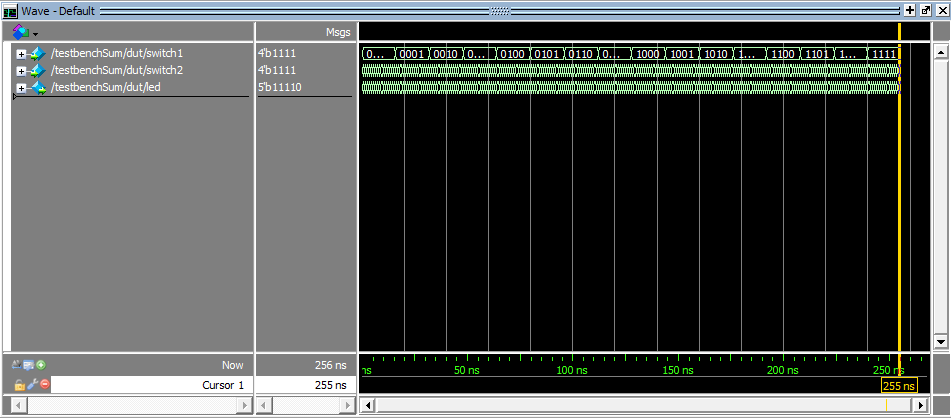
ledSum waves
AI Prototype
I gave ChatGPT the prompt, “Write SystemVerilog HDL to time multiplex a single seven segment decoder (that decodes from four bits to a common anode seven segment display) to decode two sets of input bits and drive two sets of seven output bits.” and got the follwoing code:
    module seven_seg_multiplexer (
        input logic clk,
        input logic reset,
        input logic [3:0] in1,  // Input for display 1
        input logic [3:0] in2,  // Input for display 2
        output logic [6:0] seg, // 7-segment outputs (a to g), active low
        output logic [1:0] an   // Display enable signals (active low)
    );

    // Internal signal to track which digit is active
    logic select;  // 0 -> display 1, 1 -> display 2
    logic [3:0] digit;
    logic [6:0] seg_out;

    // Simple clock divider for multiplexing (~1 kHz)
    logic [15:0] clk_div;

    always_ff @(posedge clk or posedge reset) begin
        if (reset) begin
            clk_div <= 0;
            select <= 0;
        end else begin
            clk_div <= clk_div + 1;
            if (clk_div == 0)
                select <= ~select;
        end
    end

    // Choose which digit to decode
    always_comb begin
        case (select)
            1'b0: digit = in1;
            1'b1: digit = in2;
            default: digit = 4'b0000;
        endcase
    end

    // 7-segment decoder (active low for common anode)
    always_comb begin
        case (digit)
            4'h0: seg_out = 7'b0000001;
            4'h1: seg_out = 7'b1001111;
            4'h2: seg_out = 7'b0010010;
            4'h3: seg_out = 7'b0000110;
            4'h4: seg_out = 7'b1001100;
            4'h5: seg_out = 7'b0100100;
            4'h6: seg_out = 7'b0100000;
            4'h7: seg_out = 7'b0001111;
            4'h8: seg_out = 7'b0000000;
            4'h9: seg_out = 7'b0000100;
            4'hA: seg_out = 7'b0001000;
            4'hB: seg_out = 7'b1100000;
            4'hC: seg_out = 7'b0110001;
            4'hD: seg_out = 7'b1000010;
            4'hE: seg_out = 7'b0110000;
            4'hF: seg_out = 7'b0111000;
            default: seg_out = 7'b1111111;  // Blank
        endcase
    end

    // Output assignment
    always_comb begin
        seg = seg_out;

        case (select)
            1'b0: an = 2'b10;  // Enable display 0 (active low)
            1'b1: an = 2'b01;  // Enable display 1 (active low)
            default: an = 2'b11;
        endcase
    end

endmodule
I then synthesized it and to my surprise it actually compiled. I also asked ChatGPT to give me a testbench. The test bench ultimately failed so there must be a mistake in the actual code. I did notice that ChatGPT only gave me the top module and basically put the entire lab into 1 file which is a huge mistake in this class.
I then asked a different ChatGPT the following prompt, “Write SystemVerilog HDL to time multiplex a single seven segment decoder (that decodes from four bits to a common anode seven segment display) to decode two sets of input bits and drive two sets of seven output bits. Use the seven segment decoder and oscillator provided in the attached files.” Here is the code it produced:
    // seven_seg_multiplexer.sv
    // Time-multiplex a single seven-seg decoder to drive two separate displays.
    //
    // Assumptions:
    //  - Target displays are common-anode (segment outputs are active-low).
    //  - Provided modules:
    //      * oscillator with output named "osc_out" (1-bit clock-like signal)
    //      * seven_seg_decoder with ports (input  [3:0] bcd, output [6:0] segments)
    //    If your provided module names/port names differ, adjust the instantiations.
    //  - Inputs: in1 -> physical display 0, in2 -> physical display 1
    //  - "an" outputs are active-low enables for each display (an[0] -> display 0, an[1] -> display 1)

    module seven_seg_multiplexer (
        input  logic       clk,    // primary system clock (not strictly required if oscillator used)
        input  logic       reset,  // synchronous active-high reset
        input  logic [3:0] in1,    // nibble for display 0
        input  logic [3:0] in2,    // nibble for display 1
        output logic [6:0] seg,    // segments a..g (active low)
        output logic [1:0] an      // digit enables (active low). an[0] -> display 0, an[1] -> display 1
    );

        // Internal select: 0 => show in1 on segments, 1 => show in2
        logic select;

        // Digit currently being decoded
        logic [3:0] digit;

        // Output of the external seven-seg decoder (assumed active-low segments [6:0])
        logic [6:0] seg_decoder_out;

        // Oscillator instance output (used to toggle select)
        logic osc_clk; // oscillator output (treated as a clock-like pulse)

        // Optional: If you want to use the system clock for a divider instead of oscillator,
        // comment out the oscillator instantiation and use clk_div logic below.
        //
        // Instantiate provided oscillator (adjust module/port names if different).
        // Example assumed module: module oscillator(output logic osc_out);
        oscillator u_osc (
            .osc_out(osc_clk)
        );

        // If oscillator module is not available or you prefer a divider from `clk`, uncomment:
        // logic [15:0] clk_div;
        // always_ff @(posedge clk or posedge reset) begin
        //     if (reset) clk_div <= 16'd0;
        //     else        clk_div <= clk_div + 1;
        // end
        // // use a chosen bit of clk_div as the multiplex toggle (e.g., clk_div[12])
        // assign osc_clk = clk_div[12];

        // Toggle select on rising edge of osc_clk (synchronous to osc_clk)
        // Use an edge detector to create a clean toggle on each osc_clk rising edge.
        logic osc_clk_d;
        always_ff @(posedge clk or posedge reset) begin
            if (reset) begin
                osc_clk_d <= 1'b0;
                select    <= 1'b0;
            end else begin
                // sample oscillator into clk domain (simple synchronizer)
                osc_clk_d <= osc_clk;
                // toggle select on rising edge of osc_clk (detected in clk domain)
                if (~osc_clk_d & osc_clk)
                    select <= ~select;
            end
        end

        // Choose which input nibble to decode based on select
        always_comb begin
            case (select)
                1'b0: digit = in1;
                1'b1: digit = in2;
                default: digit = 4'h0;
            endcase
        end

        // Instantiate provided 4->7 segment decoder
        // Assumed module signature: module seven_seg_decoder(input [3:0] bcd, output [6:0] segments);
        seven_seg_decoder u_decoder (
            .bcd(digit),
            .segments(seg_decoder_out)
        );

        // Drive outputs (seg and an). Segments are driven directly from the decoder (active-low).
        always_comb begin
            seg = seg_decoder_out;

            // Active-low anodes: assert the active digit low, other(s) high.
            // an[0] corresponds to in1/display 0; an[1] is in2/display 1.
            if (select == 1'b0) begin
                an = 2'b10; // enable display 0 (an[0] = 0), disable display 1 (an[1] = 1)
            end else begin
                an = 2'b01; // enable display 1 (an[1] = 0), disable display 0 (an[0] = 1)
            end
        end

    endmodule
Similar to before it only used 1 file. I created a new project and tried to synthesize the design. It failed because the path to the oscillator got messed up.
Overall, I’m surprised at how well AI did but I’m not surprised that it didn’t get the lab entirely right. One thing that probably helped the model out is that this is a pretty common project and so there are tons of open source verisions of this project online.